List of Logic Circuits
From StarMade Wiki
| This article is a work-in-progress. Edits are welcome, however please keep in mind that they may be overwritten or removed if they are not in line with the intention of the article. |
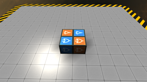
Logic Circuits are player made circuits designed to trigger the various contraptions that can be made using logic blocks. This is a semi-exhaustive list on the multitude of helpful circuits that can be built in-game and what their intended uses are.
Contents
Pulse Circuits
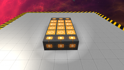
Pulse Circuits are circuits that send a signal for a set amount of time before automatically resetting. They are similar to the Button block but can be customized for longer pulses.
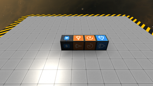
Pulse Circuit (High)
| Description | Outputs a signal that resets after 0.5 seconds. |
|---|---|
| Blocks Needed |
   
|
| Input |  High (On) Signals High (On) Signals
|
| Output |  Sends Low (Off) Signal on pulse Sends Low (Off) Signal on pulse Sends Low (Off) Signal on pulse Sends Low (Off) Signal on pulse Sends High (On) Signal on pulse Sends High (On) Signal on pulse Sends High (On) Signal on pulse Sends High (On) Signal on pulse
|
| Modifications | Connect additional DELAY-Signals to increase the time before the circuit resets. |
| How to Build | ||
|---|---|---|
| Step | Selected Block ┌┐ └┘ |
Connects to ┌┐ └┘ |
| 1 |  Activation Module |
  NOT-Signal & OR-Signal |
| 2 |  NOT-Signal |
 DELAY-Signal |
| Mod |  DELAY-Signal |
 DELAY-Signal |
| 3 |  DELAY-Signal |
 OR-Signal |
| 4 |  OR-Signal |
 Activation Module |
| 5 | Press R on the Activation Module to turn the circuit on | |
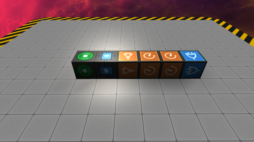
Automatic Door Circuit
| Description | Outputs a signal that resets after 1 second. Designed for automatic doors that are motion activated. |
|---|---|
| Blocks Needed |
    2x 2x 
|
| Input |  High (On) Signals High (On) Signals
|
| Output |  Sends Low (Off) Signal on pulse Sends Low (Off) Signal on pulse
|
| How to Build | ||
|---|---|---|
| Step | Selected Block ┌┐ └┘ |
Connects to ┌┐ └┘ |
| 1 | Place Trigger (Area) Controller next to Activation Module. | |
| 2 |  Activation Module |
  NOT-Signal & OR-Signal |
| 3 |  NOT-Signal |
 DELAY-Signal #1 |
| 4 |  DELAY-Signal #1 |
 DELAY-Signal #2 |
| 5 |  DELAY-Signal #2 |
 OR-Signal |
| 6 |  OR-Signal |
 Activation Module |
| 7 | Press R on the Activation Module to turn the circuit on. | |
| 8 | Place Trigger (Area)s in the desired location. | |
| 9 |  Trigger (Area) Controller |
 Trigger (Area) |
Logic Clocks
Logic Clocks are circuits that are designed to pulse a logic signal endlessly. They can be any circuit that cycles a pulse repeatedly until it has been deactivated.
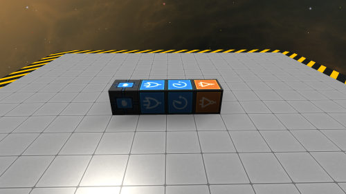
Half Second Clock (Design 1)
| Description | Outputs a signal every 0.5 seconds. | |
|---|---|---|
| Blocks Needed |
   
| |
| Input | Turn On |  Low (Off) Signal Low (Off) Signal
|
| Turn Off |  High (On) Signal High (On) Signal
| |
| Output |  Sends Low (Off) Signal on pulse Sends Low (Off) Signal on pulse Sends Low (Off) Signal on pulse Sends Low (Off) Signal on pulse Sends High (On) Signal on pulse Sends High (On) Signal on pulse
| |
| Modifications | Connect additional DELAY-Signals to increase the time between pulses. | |
| How to Build | ||
|---|---|---|
| Step | Selected Block ┌┐ └┘ |
Connects to ┌┐ └┘ |
| 1 |  Activation Module |
 OR-Signal |
| 2 |  OR-Signal |
 DELAY-Signal |
| 3 |  DELAY-Signal |
 NOT-Signal |
| 4 |  NOT-Signal |
 OR-Signal |
| 5 | Press R on the Activation Module to turn the circuit on | |
Memory Circuits
Memory Circuits are logic circuits that can remember a state for later use.
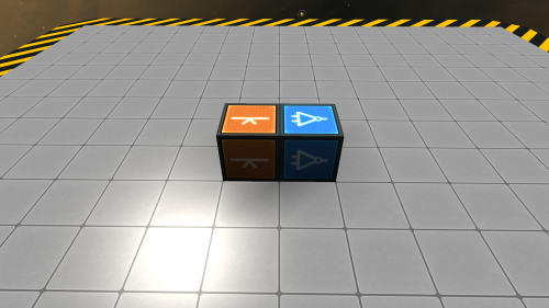
T-Flip-Flop
| Description | High signals on the Flip Flop changes the state of both the NOT-Signal and itself. Used to trigger two alternating circuits with a single input |
|---|---|
| Blocks Needed |
 
|
| Input |  High (On) Signals High (On) Signals
|
| Output |  Sends opposite signal of NOT-Signal Sends opposite signal of NOT-Signal Sends opposite signal of Flip Flop Sends opposite signal of Flip Flop
|
| How to Build | ||
|---|---|---|
| Step | Selected Block ┌┐ └┘ |
Connects to ┌┐ └┘ |
| 1 |  Flip Flop |
 NOT-Signal |
| 2 |  NOT-Signal |
 Flip Flop |
| 3 | Press R on the Flip Flop to turn the circuit on | |
RS-NOR
| How to Build | ||
|---|---|---|
| Step | Selected Block ┌┐ └┘ |
Connects to ┌┐ └┘ |
| 1 |  OR-Signal #1 |
 NOT-Signal #1 |
| 2 |  OR-Signal #2 |
 NOT-Signal #2 |
| 3 |  NOT-Signal #1 |
 OR-Signal #2 |
| 4 |  NOT-Signal #2 |
 OR-Signal #1 |
| 5 | Press R twice on either OR-Signal to turn the circuit on | |
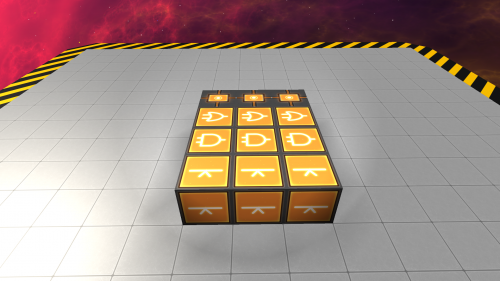
3-Input Toggle(Design 1)
| How to Build | ||
|---|---|---|
| Step | Selected Block ┌┐ └┘ |
Connects to ┌┐ └┘ |
| 1 |  Activation Module |
 DELAY-Signal #1 |
| 2 |  DELAY-Signal #1 |
 DELAY-Signal #2 |
| 3 |  DELAY-Signal #2 |
 AND-Signal |
| 4 |  AND-Signal |
 Button |
| 5 |  Button |
 Activation Module |
| 6 |  OR-Signal |
 AND-Signal |
| 7 | Repeat steps 1-6 two more times with the other columns of blocks. | |
| MOD | Repeat steps 1-6 as many times are you wish to create additional columns. | |
| 8 |  Column #1's Activation Module |
  Column #2 & #3's OR-Signal |
| 9 |  Column #2's Activation Module |
  Column #1 & #3's OR-Signal |
| 10 |  Column #3's Activation Module |
  Column #2 & #1's OR-Signal |
| MOD |  Column #X's Activation Module |
 All other column's OR-Signal |
3-Input Toggle(Design 2)
| How to Build | ||
|---|---|---|
| Step | Selected Block ┌┐ └┘ |
Connects to ┌┐ └┘ |
| 1 |  Flip Flop |
  AND-Signal & Button |
| 2 |  AND-Signal |
 Flip Flop |
| 3 |  OR-Signal |
 AND-Signal |
| 4 | Repeat steps 1-3 two more times with the other columns of blocks. | |
| MOD | Repeat steps 1-3 as many times are you wish to create additional columns. | |
| 5 |  Column #1's Button |
  Column #2 & #3's OR-Signal |
| 6 |  Column #2's Button |
  Column #1 & #3's OR-Signal |
| 7 |  Column #3's Button |
  Column #1 & #2's OR-Signal |
| MOD |  Column #X's Button |
 All other column's OR-Signal |


